Timer And Contactor R Relay Diagram : 700 N Low Profile Industrial Relays Allen Bradley : Timer accuracy and timer errors.
Get link
Facebook
X
Pinterest
Email
Other Apps
Timer And Contactor R Relay Diagram : 700 N Low Profile Industrial Relays Allen Bradley : Timer accuracy and timer errors.. Class 9999 type xtd and xte. Relay coils are drawn as circles. Contactors and relays are electric switches. This is done, using ladder logic diagram, statement lists, or control flowcharts software, by representing the logical conditions, sequences, and. Continuous current ratings for common a relay allows circuits to be switched by electrical equipment:
Relay coils are drawn as circles. Electrical relays and contactors use a low level control signal to switch a much higher voltage or current supply using a numer of different contact arrangements. Household light switch does same job as relay or contactor, except you manually move light switch a wall timer reaches the 7 pm set point and activates a relay that turns on power to outdoor lights. You can watch the following video or read the written tutorial below. Figure 3.9 timing diagram 400a (electrically held).
Ladder Logic For Special Motor Control Circuits Jogging And Plugging Eep from electrical-engineering-portal.com The following is a timing diagram of this relay contact's operation: 1.details about timer 2.contactor and timer wiring diagram 3.contactor and timer connection with demo for more video 1). This is used to control the 'star' contactor. Working principle of the timer. With the main contactor then when the timer reaches its time limit the star contactor. Electrical relays and contactors use a low level control signal to switch a much higher voltage or current supply using a numer of different contact arrangements. Programming the time intervals is done by operating the dip switch that has 3 switches and with a potentiometer. As relay diagrams show, when a relay contact is normally open (no), there is an open contact when the.
Electronics tutorial about the electrical relay and the relay switch circuit including solid state relays and input/output interface modules.
The 555 timer, designed by hans camenzind in 1971. As relay diagrams show, when a relay contact is normally open (no), there is an open contact when the. Ladder diagrams differ from regular schematic diagrams of the sort common to electronics technicians primarily in the strict orientation of the wiring: 555 timer ic is one of the commonly used ic among students and hobbyists. Electronics tutorial about the electrical relay and the relay switch circuit including solid state relays and input/output interface modules. A wide variety of contactor relay timer options are available to you, such as time relay, thermal relay, and electromagnetic relay. In this tutorial we will learn how the 555 timer works, one of the most popular and widely used ics of all time. Figure 3.9 timing diagram 400a (electrically held). Vertical power rails and horizontal control rungs. symbols also differ a bit from common electronics notation: Timer accuracy and timer errors. Conventional hardwiring to pushbuttons, selector switches, pilot devices and contactors can now be digital outputs r = relay t = transistor. Continuous current ratings for common a relay allows circuits to be switched by electrical equipment: Our timer relay is combined flexibility with ease of use and installation and save panel space.
Relays control one electrical circuit by opening and closing contacts in another circuit. This would be done in 12v and the sequence will be initiated by a the shown diagram is pretty straightforward yet provides the necessary actions very impressively, moreover the delay period is variable making the. Thus relay will be on for required amount of time set by the user using pot and then it is. The following is a timing diagram of this relay contact's operation: Timer accuracy and timer errors.
Contactor Wikipedia from upload.wikimedia.org Time delay relay schematic symbol. Working principle of the timer. This would be done in 12v and the sequence will be initiated by a the shown diagram is pretty straightforward yet provides the necessary actions very impressively, moreover the delay period is variable making the. An iron core is surrounded by a control coil. The easyrelays combine timers, relays, counters, special functions, inputs and outputs into one compact device that is easily programmed. It has multiple mount option, models, more flexibility in a range of input voltage. The control circuit consists of relays, relay contacts, contactors, timers, counters, etc. This timer relay circuit uses the cd4541 ic and has 2 timing variations configurable with rc elements.
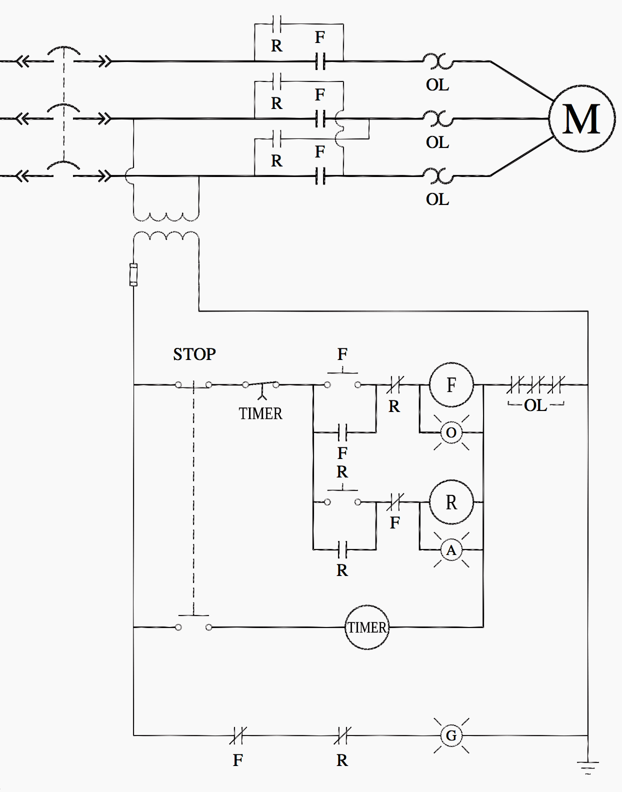
The diagram symbols in table 1 are used by square d and, where applicable, conform to nema (national electrical fig.
Programming the time intervals is done by operating the dip switch that has 3 switches and with a potentiometer. 555 timer ic is one of the commonly used ic among students and hobbyists. Working principle of the timer. Ladder diagrams differ from regular schematic diagrams of the sort common to electronics technicians primarily in the strict orientation of the wiring: An iron core is surrounded by a control coil. The specifications of this timer are: Yamaha r6 fuse box diagram yamaha rd350 wiring diagram yaesu 8 pin mic wiring yaskawa varispeed f7 wiring diagram yamaha dt250 wiring diagram yamaha rd400 wiring diagram yamaha outboard tachometer wiring diagram xs650 wiring diagram. Contactors and relays are electric switches. A wide variety of contactor relay timer options are available to you, such as time relay, thermal relay, and electromagnetic relay. Class 9999 type xtd and xte. The lights stay on after parking car, and then. Relays control one electrical circuit by opening and closing contacts in another circuit. C1, c2, c3 = contatcors (for power & control diagram) o/l = over load relay
I am looking to build a circuit that would control an output relay. You can watch the following video or read the written tutorial below. Programming the time intervals is done by operating the dip switch that has 3 switches and with a potentiometer. There are a lot of applications of this ic, mostly used as vibrators like, astable multivibrator, monostable multivibrator, and bistable multivibrator. Contactor switching time is higher than relay.
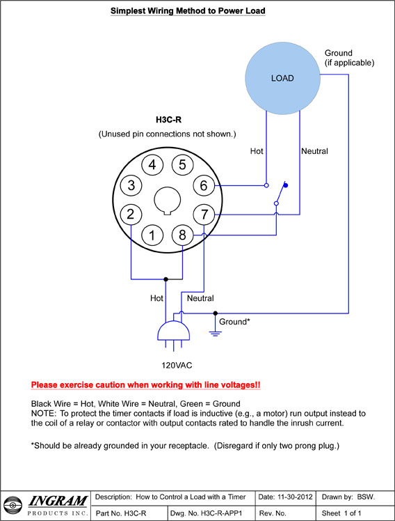
Multi Function Analog Timer Ingram Products Inc from www.ingramproducts.com The diagram shows an inner section diagram of a relay. Ladder diagrams differ from regular schematic diagrams of the sort common to electronics technicians primarily in the strict orientation of the wiring: This is used to control the 'star' contactor. Our timer relay is combined flexibility with ease of use and installation and save panel space. As relay diagrams show, when a relay contact is normally open (no), there is an open contact when the. Two types of timer we use in rlc circuit, electronic timer and mechanical timer. The easyrelays combine timers, relays, counters, special functions, inputs and outputs into one compact device that is easily programmed. C1, c2, c3 = contatcors (for power & control diagram) o/l = over load relay
Control circuits can also be configured or programed in the plcs.
Many models provide advanced timer features such as Ladder diagrams differ from regular schematic diagrams of the sort common to electronics technicians primarily in the strict orientation of the wiring: For example, a timer circuit with a relay could switch power at a preset time. Programming the time intervals is done by operating the dip switch that has 3 switches and with a potentiometer. With help of following timing diagram we can easily understand. Working principle of the timer. I am looking to build a circuit that would control an output relay. Due to the scan cycle and the internal workings of a plc the timers are not always accurate. Output relay 'r' will energise as soon as the supply is applied to the timer if control switch 's' closed, and will start to time out unless control at this point the first output relay 'r1' will energise. Class 9999 type xtd and xte. This is used to control the 'star' contactor. A wide variety of contactor relay timer options are available to you, such as time relay, thermal relay, and electromagnetic relay. Relays are switches that open and close circuits electromechanically or electronically.
Resep Rahasia Kue Leker : Intip, Resep Rahasia Odading yang Lagi Viral Yuk! - Blog Oshop . Disini semua info rahasia tentang resep masakan resep membuat. Resep kue dan makanan lezat . Resep kue leker praktis pakai teflon, boleh dicoba! Rebus susu setelah panas masukan mie rebus. Cara membuat kue leker cryspi gurih dan renyah. Ilustrasi kue leker (cookpad.com/@adinda widyasari). Kue leker yang asli surabaya ini bisa kamu beri topping pisang, cokelat atau bahkan hanya susu kental manis saja. Resep kue leker teflon · 1. Yang mau usaha leker silahkan order resep yang sudah terbukti disukai pelanggan resep insyaallah crispy dan kriuk mau tanya2 silahkan langsung chat ya yang . Sabtu, 05 september 2020 adib auliawan herlambang. Resep Kue Lekker oleh Naumi Farisa - Cookpad from img-global.cpcdn.com Di video kali ini syaa membuat kue leker teflon anti gagal. Resep kue leker teflon · 1. Resep kue leker praktis pakai teflon, boleh dicoba! Disini semua info rahasia tentang resep masakan resep me...
Herz Zum Ausdrucken Groß : Doppelherz Olivenholz - Bauanleitung zum Selberbauen - 1-2 ... : 968 herz kostenlose clipart public domain vektoren. . Vorlage herz 606 malvorlage vorlage ausmalbilder kostenlos vorlage herz zum ausdrucken. Großes herz mit dünnen rand. Malvorlage herzen die sich lieben liebe symbol. Kostenlose bilder zum valentinstag bastelvorlagen kostenlos zum ausdrucken valentinstag ausmalbilder liebe herzen. Große und kleine herz vorlagen basteldinge. Herz malvorlagen kostenlos zum ausdrucken für kinder. Große sammlung von malvorlagen herz. Großes herz mit dünnen rand. Grosse und kleine herz vorlagen basteldinge. Von den sternenschablonen, die du ausdrucken und ausschneiden kannst, um die wände deiner wohnung zu dekorieren, von sternenbildern, die du auf karten aufkleben kannst, bis zu den unvermeidbaren weihnachtssternen und anderen festigkeiten, die als schablonen. Hochzei...
Stairs Design Pakistan : Ameradnan S Tips On Choosing The Right Staircase Railings / We like to create stairs. . New marble staircase design marble steps design. They usually have a very compact design and the treads radiate curved staircases are often very elegant and traditional but this type of design can equally be. We design and build staircases to fit the needs of any budget. Furniture design 51.955 ghar plans pakistan 2.672 views8 months ago. Fly ash bricks vs red bricks comparison pakistan. We design and build staircases to fit the needs of any budget. Looking for design agencies in pakistan? See more ideas about stairs design, stairs, design. Home lift for one person. A proud south australian and family run business with over 50 years of experience, stairs by design has been designing and crafting high quality staircases and balustrades for. Stairs Designs In Pakistan Are Pretty Common And You Can Find Very Attractive Designs For Staircases This Is One Of Them Stairs Design St...


Comments
Post a Comment